How Do Technology Tanks Work?
Today, more than 2,300 water recycling, reuse and saltwater disposal operations are utilizing KBK’s patented tank technologies to remove suspended solids, gas, and oil from produced water. The HWSB™ Oil recovery tank maximizes oil recovery and the DFSD™ desanding tanks removes suspended solids and gases.
Desanding, Flow Splitting and De-Gasing
KBK’s DFSD™ (De-sanding, Flow Splitting, and De-gasing) tank was designed to capture suspended solids. As its name implies, its inlet cyclone separates particulates down to 50 microns, removing suspended solids from the inlet fluid. This concentrates most solids in one vessel, keeping the rest of the facility and its processing equipment free of any large solids during loading.
Since this fluid is likely to have periodic slugs of gas, this vessel is also designed to de-gas the inlet fluid. Gas provides enough mixing energy to defeat oil-water separation, so eliminating it is quite beneficial. Finally, the KBK DFSD™ is a hydraulic flow splitter. It can be designed with multiple splits, each one identical to the others for ideal flow division into multiple downstream systems for further processing. It usually takes a vacuum truck about one hour to remove seven feet of solids from the DFSD™. The DFSD™ can continue processing fluids during the cleaning process.
How DFSD Tanks Work:
The fluid enters the DFSD™ and is piped to the first churn tube assembly. The piping is necked down prior to entering the churn tube to increase the velocity of the fluid. The fluid is directed to spin counterclockwise in the first cone. Gas is taken from the top of the cone and piped into vapor space at the top of the DFSD™ tank. The solids fall out the bottom of the cone. The side outlet of the cone is connected to a second smaller cone.
The piping between is sized to accelerate the fluid and as the fluid enters the second cone it is directed to spin the fluid counterclockwise. Any remaining gas is taken from the top of this second cone and into the vapor area near the top of the tank. Solids fall out the bottom of the second cone. The outlet of the second cone is turned so it sends the fluid out in a counterclockwise direction along the side wall of the tank. The gas layer and gas piping from the cones is sized to handle large slugs of gas that often come from pipelines.
The outlets of the tank are designed to create enough head pressure to gravity flow to the next tank(s) in the system. These outlets are engineered to hydraulically split flows so equal volumes go to subsequent tanks. Around the bottom of the tank are a series of ports that allow a vacuum truck to connect to for removal of the captured solids. These ports allow the operator to push or pull to cause the solids to easily be removed. This tank does not require entry for cleaning. The DFSD™ reduces solids loading of the facility and the well which extends the performance of the facility.
HWSB™ Tanks: Maximizing Oil Recovery
The KBK HWSB™ (Hydrodynamic Water-Oil Separation Breakthrough) Oil Recovery tank is a significant advancement to the gun barrel and is custom engineered for your facility taking into consideration the oil and water gravities and flow velocities.
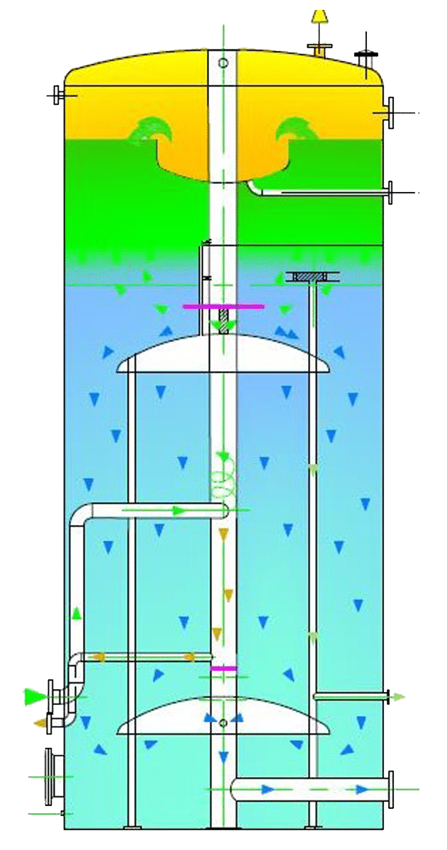
How HWSB™ Tanks Work:
The flow of water and oil liquid enter the body of the KBK HWSB™ just below the oil-water interface through a series of swirl-diverters. These diverters impart a centrifugal force on the liquids, spinning them outward from the center of the tank in an increasing radius counterclockwise spiral (a helix). The increasing radius slows the velocity of the inlet fluid and increases its effective retention time in this primary separation zone; the area just below the oil-water interface.
As the inlet fluid velocity slows, smaller and smaller droplets of oil rise through the inlet water and into the oil layer above. Since most surfaces will preferentially oil wet, and because every oil droplet that attaches to a surface is separated from the water, the KBK HWSB™ is designed so all the water contacts each interior surface. These surfaces accumulate oil, which then flows by gravity up into the oil layer above. For instance, oil droplets accumulate on the top of the upper large area flow diverting baffle, which like all surfaces, is a huge oil coalescer.
As the fluid stream spirals outward away from the center of the tank it encounters the ID of the tank wall, another large area coalescer. In fact, all the structures in the KBK HWSB™ are coalescing baffles. Any oil attaching itself to any one of these surfaces is obviously separated. As these surfaces become totally coated with oil, the oil wicks upward, eventually entering the oil layer above, adding to the volume of oil collected. All collected oil gravity flows directly to the oil sales tanks.
The oil layer is designed to provide adequate retention time to dehydrate most oil to pipeline specifications. Uniform oil collection is critical to this function, so a very large oil collector in the center of the tank at the top of the oil liquid layer assures all oil rises uniformly through the entire oil layer and is collected from 360° of that layer. The large collector is designed with a very large spillover weir. This weir, the OD of the oil collector structure, is nearly 16’ long. Its length secures a minimum level deviation even during periods of very high slug rates. The level differential between the oil outlet and the downstream tank assures that large flow rates of oil can flow out of the KBK HWSB™ oil collector and through the oversized oil outlet piping during slug flow conditions. Because of this it is nearly impossible to overflow the HWSB™.
Once the largest oil droplets have separated in the primary separation area above the upper spreader baffle, the water must turn 90° downward to flow down between the upper large baffle and the tank wall. This causes a slight acceleration through this annular area. As the downward flowing water reaches the lower edge of the baffle it enters a quadrant of the HWSB™ which is open to full diameter flow. The accelerated velocity above creates a small pressure drop through the annulus. As the fluid exist the annulus the pressure differential creates a small eddy current that pulls about half of the downward flowing water in under the large baffle, changing its direction to straight down. The remaining 50% flows straight down in the annular area.
At this point 100% of the fluids are distributed throughout 100% of the KBK HWSB™ cross section. All fluid flow is now vertically downward throughout the entire cross-sectional area of the KBK HWSB™. At this point, the flow velocity is as slow as it can be, and separation of the smallest droplets (according to Stokes’ Law) occurs. The smallest of oil droplets flow upward. These droplets coat the underside of the upper baffle. Once coated, the collected oil migrates directly into the oil layer above through a dedicated pipe extended from the underside of the upper baffle into the oil layer, preventing any further contact between the separated oil and the water.
This adds to the volume of oil collected and the separation efficiency of the KBK HWSB™. As the clarified water nears the bottom of the KBK HWSB™ it encounters a second large baffle. As the water impinges on this baffle oil droplets accumulate on its surface, further enhancing separation. Additionally, this lower baffle forces the flow stream to change directions from vertically downward to horizontal and then to slightly vertical. At this point, the water is flowing in slightly upward and straight toward the ID of the tank again. As it contacts the underside of the large baffle the smallest remaining oil droplets impinge on it and wick up into a dedicated collection area above, finally wicking up into the oil layer above. Once again, separation efficiency is enhanced.
At this point, the water enters through engineered orifices in the center column, engineered to insure uniform water flow toward this point. The water flows through the orifices, holes in the center column placed under the large baffle, where it turns downward again and flows to the outlet piping and into the annulus of the engineered water leg.
Another key feature of the HWSB™ is the adjustable water leg. The KBK water leg is engineered so that surges of fluid into the HWSB™ do not meaningfully impact the interface level in the tank. This ensures the dehydration of oil does not get interrupted.
No other atmospheric separation vessel is more efficient at removing small amounts of oil from large quantities of produced water! Replacing Gunbarrels with the KBK HWSB™s usually results in oil recovery rates five times greater than a equally sized gun barrel tank. This increase in recovered and saleable crude oil pays for the KBK HWSB™ in a matter of months, making it one of the best and easiest to justify investments you can make.
Consider that injecting 500-1000 ppm of oil is equivalent to pumping 3,000 to 6,000 pounds of well plugging “goo” into the injection well every day. That’s 547.5 to 1,095 TONS of “goo” annually. KBK’s patented SWD technology equipment improves water quality and protects the well, which makes the facility significantly more profitable.
Contact us to learn more!